TRANSFORMER OPERATION AND APPLICATIONS

Transformer is an electrical device which can move and change the electric energy from one or more electrical circuits to another through a magnetic holding and based on the electromagnetic inductions principles. The purpose of transformer is to transmit and distribute power in AC rather than in DC. The reason is, because transformer does not work in DC so there must be some difficulties to transmit power in DC.

ImageFigure 1.1 The Energy Transformation


  1. Transformer Principle

The basic principle of transformer is the mutual induction between two circuits which is connected by magnetic flux. Furthermore, transformer is consist of two induction coils which are separated in electrical way, but in magnetic way they are connected by a path .

When the primary coil of a transformer is connected to an alternating voltage, there will be a current in the primary coil called the exciting current. The exciting current sets up an alternating flux which links the turns and induces a voltage on both windings.


  1. Transformer Symbols

 Image

Figure 2.1 The Transformer Symbols


  1. Transformer Applications and Uses

There are several applications and uses of transformer which are very important.

  • Transformer can increase or decrease the level of Voltage or Current in AC circuit. In addition, when the voltage is increasing, the current will be decreasing and vice verse. Because P=V.I with the same power
  • The value of capacitor, inductor, or even resistance in AC circuit can be increased or decreased by the transformer. It also can act as the impedance transferring device.
  • Transformer can be used to prevent DC from passing one circuit to the others.
  • It can isolate two circuits electrically.

The main application of transformer is to Step up (increasing) or Step down (decreasing) the voltage level. Without transformers the widespread distribution of electrical power would be impractical. Transformers make it possible to generate power at a convenient voltage, step up to a very high voltage for long distance transmission, and then step down for practical distribution.

ImageFigure 3.1 Basic Transformer


References

Petruzella (1996). Industrial Electronics.Singapore: McGraw Hill.

Electrical Technology.(2012, February). Uses and Application of Transformer. Accessed on May 1st 2014, From http://www.electricaltechnology.org/2012/02/uses-and-application-of-transformer.html

Website Staff UI (2010).TRANSFORMER PAPERS. Accessed on May 1st 2014, from staff.ui.ac.id/system/files/users/…/transformerpaper.pdf

http://www.g3npf.co.uk/transformers.htm


GROUNDING SYSTEM

Grounding System is a system of safeguards against devices which use electricity as the energy sourcefrom surges of lightning. Grounding system also descirbed as a relation between an electrical circuit or equipment with the earth (ground).


Image

Figure 1.1 Grounding for protection

  1. Service Grounding
  • Ground                                : a conducting connection between an electrical circuit and the earth, or to a conducting body that serves in place of earth.
  • Grounding Conductor         : a conductor used to connect equipment or the grounded (neutral) conductor of the system to the ground.
  • Grounding Electrode          : the metal components which comprise the method of grounding the wiring system to earth. For the example is water pipe, metal rod, etc.
  • Bonding                              : the joining metal components to form a conductive path.
  • Water Meter Bonding        : continuity of the ground path or bonding connection shall not rely on water meters. Effective bonding shall be provided around equipment which may be removed for repair or replacement.
  1. The Purpose Of Grounding System

Based on IEEE Std 142™-2007, they are two purposes of grounding system.

  • Limiting the magnitude of voltage toward the earth to be in the allowed limits
  • Provide a path for the current flow which can provides detection of the undesirable relationship occurrence between the conductor system and the earth. This detection will cause the operation of an automatic gear which decides the voltage supply for the conductor.
  1. The Characteristics Of Effective Grounding System
  • Well planned, all connections which are found on the system must be a previously planned connection with specific norms.
  • The visual verification can be done.
  • Avoid the trouble which happen to the electrical current from the device.
  • All of the metal components have to be fastened by the grounding system, in order to minimize the electrical current through conductive material at the same electric potential.

An ungrounded power tool can kill you. Always use appropriate grounded power tools. Use only those power tools with three pronged plugs or double insulated tools with two pronged plugs. Inspect cords and equipment often to make sure that ground pins are in the safe condition.

References         :

Mark J. Reinmiller, P.E. (1992).”Introduction to Electrical Grounding”. Journal of ASHI Technical Journal.34-35.

http://digilib.unimus.ac.id/files/disk1/119/jtptunimus-gdl-muhamatyas-5924-3-babii.pdf

Petruzella (1996). Industrial Electronics.Singapore: McGraw Hill.

SINGLE LINE AND BLOCK DIAGRAM

For every electrical engineer or even technician it’s very important to understand about circuit diagram, whether in engineering design activity, maintenance, and troubleshooting . First of all, circuit diagram is a figure or direction about the components inside an electrical circuit, also about those components functions, and the relation with the circuit.

            Thus, if an engineer or technician understands about the circuit diagram, He/she will capable to design a circuit correctly or analyze the error toward the circuit. The two example of circuit diagrams are Single Line and Block Diagram.


SINGLE LINE DIAGRAM

            Single Line Diagram is the simplest diagram rather than other diagrams, where only the information about a circuit is required, but the detail of the actual wire connections and operations of the circuit are not . Electrical elements such as circuit breakers, transformers, capacitors, bus bars, and conductors are shown by standardized schematic symbols.

            This diagram uses single lines and graphic symbols to indicate the path and components of an electrical circuit.. Single line diagram usually use to describes a complex circuit by simplifying the figure into a circuit flow, So it will be easier for engineer or technician to read the circuit system. This diagram often use to show the main switch and the design of switch equipments.

One example of Single Diagram is shown on the figure below:

Image

                        Figure 1 . Single Line Diagram


BLOCK DIAGRAM

 A block diagram of a system is a pictorial representation of the functions perfomed by each component and of the flow of signals. (Ogata, Katsuhiko. 2002. Modern Control Engineering. 4th Ed.)

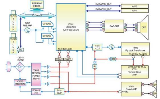
            Block Diagram indicates most of parts from complex electronic or electrical system which are served in blocks. Furthermore, in this diagram the individual components and wires are not shown, where each block represents the electrical circuit that has some certain functions.

            The block diagram is mostly used for higher level rather than single line diagram. It has less detailed description in order to undertand the overall concepts more and less at understanding the implementation details.The blocks or boxes usually contains a description and the name of the component, or the symbol for the mathematical operation that should be performed in the input to generate the output. This diagram is usually implemented in the engineering world in hardware design, electronic design, software design, and process flow diagrams.

One example of Block Diagram is shown on the picture below:

 Image

                                                 Figure 2. Block Diagram


References:

  1. http://en.wikipedia.org/wiki/Block_diagram
  2. http://en.wikipedia.org/wiki/One-line_diagram
  3. http://pampam-7.blogspot.com/2012/04/pengertian-diagram-blok.html
  4. http://irfansigaraxxx.blogspot.com/2011/07/mengenal-diagram-rangkaian-listrik.html
  5. http://muhammad-salehuddin.blogspot.com/2010/01/block-diagram-diagram-blok.html