ROBOTICS

                 The history of industrial automation is characterized by periods of rapid change in popular methods. Either as a cause or, perhaps, an effect, such periods of change in automation techniques seem closely tied world economics. Use of the industrial robot, which became identifiable as a unique device in the 1960s, along with computer-aided design (CAD) systems and computer-aided manufacturing (CAM) systems, characterizes the latest trends in the automation of the manufacturing process. These technologies are leading industrial automation through another transition, the scope of which is still unknown.

                Robots are computer controlled devices which perform tasks usually done by humans. The basic industrial robot in wide use today is an arm or manipulator which moves to perform industrial operations. Tasks are specialized and vary tremendously. They include       :

  • Handling. Loading and unloading components onto machines.
  • Processing. Machining, drilling, painting, and coating.
  • Assembling. Placing and locating a part in another compartment.
  • Dismantling. Breaking down the object into its component parts.
  • Welding. Assembling objects permanently by arc welding or spot welding.
  • Transporting. Moving materials and parts.
  • Painting. Spray painting parts.
  • Hazardous tasks. Operating under high levels of heat, dust, radioactivity, noise, and noxious odors.


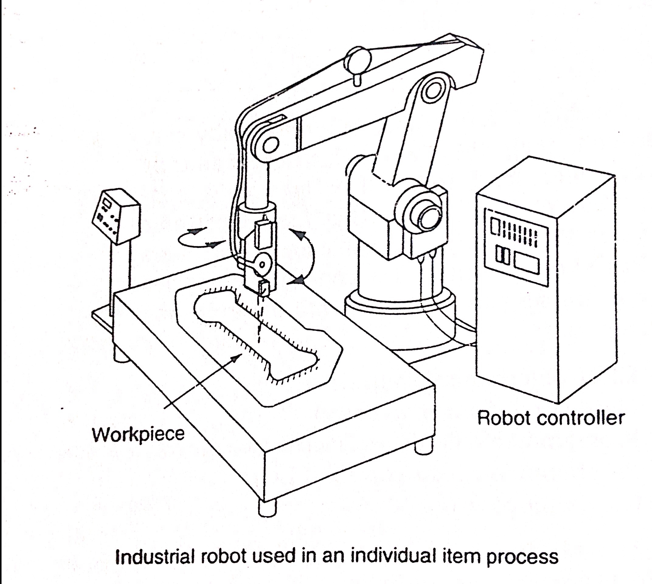
These figures below are the example of Industrial Robotics.

Image             
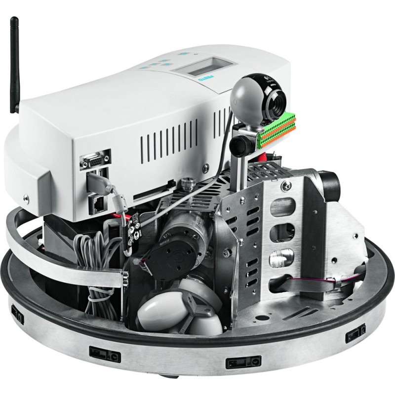
Figure 1.1 Mobile Robotics  (Robotino) 

Image                 

Figure 1.2 Arm Robot


Robotics Controllers

The controller contains the power supply, operator controls, control circuitry, and memory that direct the operation and motion of the robot and communication with external devices. Functionally, the controller has three major tasks to perform. Which are        :

  • Provide motion control signals for the manipulator unit (also known as signal processing).
  • Provide storage for programmed events.
  • Interpret input/output signals, including operator instructions.

In general, the controller includes the following devices that are used to operate the system:

  • Operator panel
  • Teach pendant
  • CRT Screen and keyboard.

The robotic controller is a microprocessor based system that operates in conjunction with input and output cards or modules. With growing use of computers and PLCs in industry, the robot controller has become more important than the manipulator it controls. The robot controller is now required to communicate with devices outside itself such as PLCs and the plant computer systems.


References         :

Petruzella (1996). Industrial Electronics.Singapore: McGraw Hill.

John J. Craig (2005). Introduction to Robotics: Mechanics and Control.United States of America: Pearson Prentice Hall.

http://www.robotshop.com/ca/en/festo-robotino-mobile-robotic.html (Figure 1.1)

http://www.adafruit.com/blog/2012/09/07/raspberry-pi-owi-robotic-arm-edge-usb-protocol-and-sample-code-piday-raspberrypi-raspberry_pi/ (Figure 1.2)

PROGRAMMABLE LOGIC CONTROLLER (PLC)

Control engineering has evolved over time. In the past humans were the main method for controlling system. More recently electricity has been used for control and early electrical control was based on relays. These relays allow power to be switched on and off without a mechanical switch. It is common to use relays to make simple logical control decisions. The development of low cost computer has brought the most recent revolution, the Programmable Logic Controller (PLC). The advent of the PLC began in the 1970s and has become the most common choice for manufacturing controls.

                A programmable logic controller is a computer designed for use in machines. Unlike a computer, it has been designed to operate in industrial environment and is equipped with special inputs/outputs and a control programming language.

                PLCs have been gaining popularity on the factory flow and will probably remain predominant for some time to come. Most of this is because of the advantages they offer.

  • Cost effective for controlling complex systems.
  • Flexible and can be reapplied to control other systems quickly and easily.
  • Computational abilities allow more sophisticated control.
  • Trouble shooting aids make programming easier and reduce downtime.

Reliable components make these likely operate for years before failure.

TYPES OF PLC

Image

The Advantages Of PLC

  • High Flexibility
  • High Efficiency in installation and wiring   cost.
  • Easy in trouble shooting and error analysis
  • The program that already made can be easily storage in various media (hardisk, USB      flash drive, etc)
  • The program can be copied easily
  • The program can be printed


Memory

Memory can be placed into two categories:

  1. Volatile                : Memory will lost its store information if all operating power is lost or remove. Volatile memory is easily alter and quite suitable for most application when supported by battery backup.
  2. Non Volatile      : can certain store information when power is removed accidentally or intentionally.


PLC Configuration System

  1. Input (Sensing)
  2. Processing
  3. Output (Action)

Image

 References  :

Petruzella (1996). Industrial Electronics.Singapore: McGraw Hill.

Click to access plc_intro.pdf

TYPE OF PROCESS

               The types of process carried out in modern manufacturing industries can be grouped into three general areas, in terms of the kind of operation that takes place as               :

  • Continuous process
  • Batch production
  • Individual products production


                Continuous Process

                A continuous process is one in which raw materials enter one end of the system and the finished product comes out the other end of the system. The process itself runs continuously. Once the process commences, it is continuous for a relatively long period of time. The time period may be measured in minutes, days, or even months, depending upon the process.


 Image

Figure 1.1 Continuous Process


               Batch Production

                In batch processing there is no flow or product material from one section of the process to another. Instead, a set amount of each of the inputs to the process is received in a batch, and then some operation is performed on the batch to produce a finished product or an intermediate product which needs further processing. The process is carried out, the finished product is stored, and another batch of product is produce. Each batch of produce may be different.

 Image

Figure 1.2 Batch Production


            The Individual Product Production

             The individual product production process is the most common of all processing systems. With this manufacturing process, a series of operations produces a useful output product. The item being produced may be required to be bent, drilled, welded, and so on ,at different steps in the process. The workpiece is normally a discrete part that must be handled on an individuals basis.

 Image

Figure 1.3 Individual Product Production


          References

          Petruzella (1996). Industrial Electronics.Singapore: McGraw Hill.

PRESSURE CONTROL

                Pressure control may either control (maintain the pressure of gas, liquid, or solid at some specified value) or limit (sense that pressure has reached some preset limit or is moving out of some safe range). Pressure is defined as the force per unit area. The most common units of pressure are pounds per square inch (psi), inches of water column (wc) in a manometer, or inches of mercury (Hg). The most popular metric unit of measurement is the kilo-pascal (kPa).

                Pressure is one of the most important industrial process variables. A normally closed pressure switch contact that opens on rising pressure is used. This pressure switch operates to signal the return of the pneumatic (air) cylinder. The advantage of using pressure switch over a limit switch is that the workpiece will always receive the same amount of pressure before the cylinder returns. The pressure switch is used to transfer information concerning pressure to an electric circuit.


Important pressure switch specifications include              :

  • Adjustable operating range
  • Adjustable differential range
  • Set point repeatability
  • Enclosure type
  • Electrical rating
  • Switch arrangement


Figure 1.1 Pressure Control Switch

Image

References  :

Petruzella (1996). Industrial Electronics.Singapore: McGraw Hill.

http://www.ecvv.com/product/1988334.html

MOTOR STARTING

                The electric motors operate on magnetism. The amount of current needed to create magnetism depends on the size and design of the motor. Motors are rated in horsepower or watts. The higher the rating of the motor, the higher the starting and running currents will be.

                Motor Starting is a vital component inside the starting system. Without the starting motor, the engine can’t be worked. Motor starting converts electrical energy through a battery into mechanical rotating energy. These motor work under heavy load. The main function of motor starting is to move the flywheel movement for starting the engine. The picture below illustrates about the motor starting construction. They produce big power in a short time and in a small volume. In addition, if the starter motor fault occurred, the device can’t be run, especially in emergency devices.

 Image

Figure 1.1 Motor Starting Construction


  • Full Voltage Starting Of AC Induction Motors

A full voltage or across the line, starter is designed to apply full line voltage to the motor upon starting. Full voltage starters may be either manual or magnetic.


                Manual Starter

                Manual starters are often used for small motors, those up to about 10 hp. They consist of a switch with one set of contacts for each phase and a thermal overload device.


                Magnetic Across The Line Starter

                This is operated by an electromagnetic or a solenoid. A manual starter must be mounted so that is easily within reach of the machine operator. With magnetic control, push button stations are mounted nearby, but automatic control pilot devices can be            mounted almost anywhere on the machine.


  • Reduced Voltage Starters

There are two primary reasons for using a reduced voltage when starting a motor            :

  • It limits line disturbances.
  • It reduces excessive torque to the driven equipment.

When a reduced voltage is applied to a motor rest, both the current drawn by a motor and the torque produced by the motor are reduced

  • DC Motor Control

Direct current (DC) motors are used far less than AC units (they need special starting equipment). With a DC magnetic motor starter, it’s important to realize that the breaking of the power circuit produces an arc, which will burn the power contacts if not extinguished quickly. To help extinguish the arc, the starter is equipped with three power contacts connected in series.

  • Electric Clutch

In general, an electric clutch consists of an electromagnet disc and an armature disc

Electric clutches are usually used to         :

o   Engage very large motors to their loads after the motors have reached running speeds.

o   Provide smooth starts for operations in which the material being processed might be damaged by abrupt starts.

o   Start high inertia loads when starting may be difficult for a motor that is sized to handle only the running load.


References

Petruzella (1996). Industrial Electronics.Singapore: McGraw Hill.

Murugesan V. M., Chandramohan G., Senthil Kumar M., Rudramoorthy R., Ashok Kumar L., Suresh ,Kumar R.,Basha D. and Vishnu Murthy K.(2012).”Overview Of Automobile Starting System Faults and Fault Diagnosis Methods”. Journal of Engineering and Applied Sciences.7.812-819.


MAGNETIC CONTACTORS

            The mechanical endurance is the critical characteristic of Magnetic Contactors, which are widely used in such industrial equipments as elevators, cranes, and factory control rooms in order to close and open the control circuit.

            Magnetic contactors are mainly located in the end of the power distribution system, meaning the nearest position of the electrical load. Magnetic Contactors are composed of a magnetic component, a contact point and some frames to hold them which is illustrated in figure 1.1.

ImageFigure 1.1 A Schematic Diagram Of Magnetic Contactors

            The voltage and current capacity of the magnetic switches for alternating current range from 220V-11A to 690V-5A and also from 220V-800A to 690V-630A, respectively. In the field operation, the magnetic switches are generally used below 690V-800A.

                Magnetic contactor consists of electromagnetic coil, several stationary contacts, and auxiliary contacts (NO contacts and NC contacts). The function of stationary contacts is as a connector between terminal motor with the voltage source. Stationary contacts have larger contact and those are on a center position. These contacts are shown with 1,2,3,4,5,6 symbols. Auxiliary contacts serve as the part of control circuit. Among its function is as the locker and as contacts to lamp indicators. These contacts are shown with 11,12,13,14 symbols for NO and 21,22,23,24, and so on for NC. But the last number is always 1 until 4. The magnetic coil are shown with A1-A2 symbols which will work , if the coil gets the voltage source.

 Image

Figure 1.2 Magnetic Contactor

The Characteristics Of Magnetic Contactor

a.            The power capability of contactor must be written in Watt/KW which is adapted by the load.

b.            The ability to draw the current from the contacts, Written in ampere .

c.             The ability of voltage from the magnetic coil, whether for 127 volt or 220 volt, so also its frequency.

d.            The ability to protect against the low voltage.


The Applications of Magnetic Contactors

a.     Lighting control

Contactors are often used to provide central control of large lighting installations, such as an office building or retail building. To reduce power consumption in the contactor coils, latching contactors are used, which have two operating coils. One coil, momentarily energized, closes the power circuit contacts, which are then mechanically held closed; the second coil opens the contacts.

b.     Magnetic starter

A magnetic starter is a device designed to provide power to electric motors. It includes a contactor as an essential component, while also providing power-cutoff, under-voltage, and overload protection.

c.      Vacuum contactor

Vacuum contactors utilize vacuum bottle encapsulated contacts to suppress the arc. This arc suppression allows the contacts to be much smaller and use less space than air break contacts at higher currents. As the contacts are encapsulated, vacuum contactors are used fairly extensively in dirty applications, such as mining.

d.     PLC(programmable logic control)

With magnetic contactors, automatic and semiautomatic control is possible with equipment such as programmable logic controllers.

References      :

Petruzella (1996). Industrial Electronics.Singapore: McGraw Hill.

Haeng-Soo Ryu, Gyu-Hwan Han, and Nam-Sik Yoon. (2007).”Basic Study of Degradation Test for Magnetic Contactors and Reliability Centered Maintenance”. Journal of Electrical Engineering and Technology.2.441-444.

ELECTRO MECHANICAL CONTROL RELAY

In electronics field, relay is known as the component which is implementing the switching logic. Before 70’s, relay is the brain of circuit controller. But after that, PLC was replacing the relay position. The simplest relay is the electromechanical relay which gives the mechanic movement when received the electric source. Furthermore, electromechanical relay (EMR) is a magnetic switch. It turns a load circuit ON or OFF by energizing an electromagnet, which opens or closes contacts in the circuit.

                The EMR has a large variety of applications in both electric and electronic circuits. For example, EMRs may be used in the control of fluid power valves and in many machine sequence controls such as drilling, boring, milling, and grinding operations. Electromechanical relays contain both stationary and moving contacts. The moving contacts are attached to the plunger. Contacts are referred to as normally open (NO) and normally close (NC).

Image

Figure 1.1 Basic Contact Forms

Image

Figure 1.2 Electromechanical Relay

  • Normally open contacts are open when no current flows through the coil but closed as soon as the coil conducts a current or is energized.
  • Normally close contacts are closed when the coil is deenergized and open when the coil is energized.

In general, relay is used for accomplish these functions:

  • Remote Control               : It can turn on or turn off the device from distance.
  • Power Amplification      : Amplified the current or the voltage. Example: starting relay in car machine
  • As the logic controller in a system

Many EMRs contain several sets of contacts operated by a single coil. Such relays are used to control several switching operations by a single, separate current. In general, control relays are used as auxiliary devices to switch control circuits and loads such as small motors, solenoids, and pilot lights. The EMR can be used to control a high voltage load circuit with a low voltage control circuit. This is possible because the coil and contacts of the relay are electrically insulated from each other.

Another basic application for a relay is to control a high current load circuit with a low current control circuit. This is possible because the current that can be handled by the contacts can be much greater than what is required ti operate the coil.


References         :

http://www.oenindia.com/pdf/relays_Technical_Write_up.pdf

Petruzella (1996). Industrial Electronics.Singapore: McGraw Hill.

http://info.ee.surrey.ac.uk/Workshop/advice/coils/force.html

ALTERNATING CURRENT GENERATORS

Alternating Current (AC) generator is the most important means of producing electrical power. Because most of the electrical power used aboard Navy ships and aircraft as well as in civilian applications is AC. AC generators, generally called alternators, vary greatly in size depending upon the load to which they supply power. For example, the alternators in use at hydroelectric plants, such as Hoover Dam which are tremendous in size, generating thousands of kilowatts at very high voltage levels.

 AC Generator Principle Of Operation

Alternating current (AC) generators also called synchronous generatorsare the primary source of all the electric energy we consume. These machines are the largest energy converters in the world. Generator is a machine that uses magnetism to convert mechanical energy into electric energy. The figure 1.1 shows us about the principle of an AC generator operation. A wire loop rotates within the magentic field generated by a magnet, which induces an AC voltage between the loop terminals.

 Image

Figure 1.1 AC Generator

Image

Figure 1.2 AC Generator Output

The amuont of voltage induced in a conductor as it moves through a magnetic field depends on:

  • The strength of the magnetic field. The stronger the field the more voltage induced.
  • The speed at which the conductor cuts through the flux. Increasing the conductor speed increases the amount of the voltage induced.
  • The angle at which the conductor cuts the flux. Maximum voltage is induced when the conductor cuts the flux at 90­0 , and less voltage is induced when the angle is less than 900.
  • The length of the conductor in magnetic field. If the conductor is wound into a coil of several turns, its effective length increases, and so the induced voltage will increase.        

Alternating current generators are built with either a stationary or a rotating dc magnetic field. The stationary field type is usually of relatively small kilovolt-ampere capacity and low voltage rating.


References

Petruzella (1996). Industrial Electronics.Singapore: McGraw Hill.

Portela P., Sepulveda J., Esteves J.S. (2008).”The Hands-on Science Network”. Journal of Alternating Current and Direct Current Generator.1.44-46.

Click to access ac%20generators%20and%20motors.pdf

THYSISTORS

Thysistors is the other name of door in greek, because the thyritors properties which similar with a gate that can be opened and closed to drain the electrical current. In addition, thyristor is a semiconductor componenet for switching which based on the PN junction structure. Thyristor has a stabilization in two states (ON and OFF), and has internal regeneration feedback. There are several components which included as thyristors, such as PUT (programmable uni-junction transistor), UJT (uni-junction transistor ), GTO (gate turn off switch), photo SCR, etc.

                   Thyristors Symbols

          The figure below shows us about the most commonly used schematic symbols for Thyristors:

ImageFigure 1.1 The Thyristors Symbols


                Thyristors Structures

          The main characteristic of thyristor is the component that made from silicon semiconductor. The P-N junction structure of thyristor is more complex than the bipolar transistor or MOS. The thyristor component usually use as a switch. The basic structure of Thyristor is 4 layers PNPN structure which is shown in the figure below.

ImageFigure 2.1 Thyristor Structure

 In this article will be discussed about the most frequently used thyristor devices, they are Silicon Controlled Rectifiers and TRIAC. Both SCR and TRIAC are the members of thyristor familiy. SCR is unidirectional device where TRIAC is bidirectional. Silicon Controlled Rectifiers are designed to switch the load current in one direction, while a TRIAC is designed to conduct the load current in either direction.

References

Petruzella (1996). Industrial Electronics.Singapore: McGraw Hill.

Click to access HBD855-D.PDF

http://www.electroniclab.com/index.php/labelka/11-thyristor

PROXIMITY SENSOR

Nowadays, most processes in industrial environments are rely on monitoring systems to make sure the product quality and process efficiency . obtaining reliable results depends on choosing the proper sensor technology for the application. To accomplish theses demands, sensors have to be durable, flexible, and reliable, regardless of the industrial environment. Appropriate sensor selection requires careful consideration of the sensor’s capabilities, limitations, and suitability for the intended application.

Proximity sensors cover a divers range of sensing capabilities, because their versatillity and high level of functionality. There are several popular proximity sensor types, such as inductive, capacitive, optical, radar, and vision sensors.

                What is PROXIMITY SENSOR?

            Proximity sensors or also called proximity switches detect the presence of objects or workpieces without physical contact. In additon, proximity sensors are automatic sensors or switches which detect object based on the proper distance. The characteristic of this sensors are detecting a very close object with milimeter as the unit.

Image

Figure 1.1 Proximity Sensors


PROXIMITY SENSORS ARE USED WHEN         :

  • The object being detected is too small, too lightweight, or too soft to operate a mechanical switch.
  • Rapid response and high switching rates are required, as in counting or ejection control applications.
  • An object has to be sensed through non-metallic barriers such as glass, plastic, and paper cartons.
  • Hostile environments demand improved sealing properties, preventing proper operation of mechanical switches.
  • Long life and reliable services are required.
  • A fast electronic control system requires a bounce-free input signal.


THE TYPES OF PROXIMITY SENSORS

  • Inductive Proximity Sensor 

Inductive proximity sensors plan a special important role owing to their non contact mode of operation, their robust industry compatible construction and the resulting high degree of reliability as well as for economic reason. Furthermore, the inductive sensor is a sensing device that is actuated by metal object.

ImageFigure 3.1 Inductive Sensors

  • Magnetic Sensors or Switches

Magnetic swtich contact or usually called as reed relay is composed of teo flat contact tabs which are hermetically sealed (airtight) in a glass tube filled with protective gas.

ImageFigure 3.2 Magnetic Sensors

  • Ultrasonic Sensors

Ultrasonic sensor operate by sending sound waves against the target and measuring the time it takes for the pulses to bounce back. The ultrasonic sensing techniques have become mature and are widely used on various engineering fields and basic science.

ImageFigure 3.1 Inductive Sensors

THE APPLICATIONS OF PROXIMITY SENSORS

  • Conveyor Systems
  • Automated Guieded Vehicle Systems
  • Parking Sensors
  • Ground Proximity Warning System
  • Roller Coasters

REFERENCES:

Petruzella (1996). Industrial Electronics.Singapore: McGraw Hill.

http://mcweb.nagaokaut.ac.jp/~ihara/column/ultrasonic%20sensors%20draft.pdf

http://stevenengineering.com/Tech_Support/PDFs/23ISPROXS.pdf

http://www.fargocontrols.com/sensors.html

www.legoengineering.com